DOM Tubing Process
DOM tubing is actually not technically a tube at all. Actually, it is the process from which DOM tube is formed. Drawn Over Mandrel is a metal forming process. It starts with an electrically welded formed tube (ERW). The ERW is cold drawn through a die and over the sides of a mandrel. Thus, the die size and angle determines the Outside Diameter (ID) and Mandrel (Plug) determines the Inside Diameter (ID). Afterwards, multiple applications (passes) further forms and refines the finish and mechanical properties necessary for its final application.
Drawn Over Mandrel
Drawn Over Mandrel is one of many tube milling techniques. There are other similar Cold Tube Drawing methods to size and finish tube to desired dimensions. DOM Tubing starts out as a Hollow or CREW (Cold-Rolled ERW tube).
Firstly, the larger ERW tube is “pointed” in order to be grabbed by a trolley jaw. The trolley is a conveyor-like platform which pulls the tube through the die. After “Pointing” of the raw tube, a carbide mandrel is inserted inside the tube’s bore. Then, the tube is set inside a carbide die. After which, a solvent lubricates the tube’s surface. Then, the trolley jaws grip the tube at pointing end pulling via the trolley hook drawing the pipe through the die.
As a newly resized DOM tube, ultimately the die and mandrel determines the OD (Outside Diameter) and ID (Inside Diameter) of the final tube. In other words, a high-angle die will thin a heavy-wall tube while a low-angle die will thicken a thin-wall tube. Optimum die positioning and its angle determines correct diameter-to-thickness (D/t) ratio.
Multiple Passes
Multiple passes (Iterations) may be necessary depending on DOM method, tube size, finish, and metallurgical and mechanical requirements. For example, if the amount of reduction necessary for the finished tube is such that it requires several incremental reductions. After which, additional surface treatments may be deemed necessary as well.
Mandrel and Rod Removal
Now that the tube has completed its first drawn, the mandrel needs to be removed. But how do you get the mandrel, and or rod, out from inside the tube? Well, there is another step that expands the tube. One method is to apply pressure to the rotating tube over a series of rollers. This action stresses the tube and expands it enough to extract the mandrel. Additional drawing process may follow until the correct finish is successful.
Computer Aided Design (CAD)
Unlike in the past, trial and error has been replaced with Computer Aided Design (CAD). With the assistance of CAD, die design has vastly improved. Therefore, drawing processes have experienced many improvements. As a result, productivity has increased, lead times shortened, and costs have reduced. For example, determining the precise die angle, both thick-wall tubes and thin-wall tubes is achievable without wasted time and costs.
Finite Element Method (FEM)
“Finite Element Method (FEM) is one of the most important methods to simulate metal forming.” (Neves, Button, Caminaga, Gentile p.426, 2005).2 FEM is being used to compute the resulting product based on temperature, pressure, material, and other production factors. Modeling and simulation technology has replaced trial and error.
One such software that uses FEM is MSC SuperForm. Used by engineers and designers alike, this software can simulate material flow, stresses, forming pressures, and trimming. With that information, engineers and tool designers can determine precise die and mandrel angle and shape, lubrication, and other cost-saving factors.
Cold Drawing Examples
Cold drawing processes’ variables to consider include the die and mandrel geometry, material properties, and the resulting reduction achieved. Below are some of the most common DOM tubing manufacturing methods. Tube Sinking, Rod Drawing (DOM), Fixed Plug Drawing, Floating Plug Drawing, and Tethered Plug Drawing are described below. The latter being a mix between Floating and Fixed. Generally speaking, Tube Drawing is sizing a tube blank by narrowing (or shrinking) a larger tube (or hollow) by pulling or pushing (drawing) it through a smaller diameter die. The mandrel (or plug) maintains the tubes’ shape (and inside diameter) while the die reduces its overall diameter.
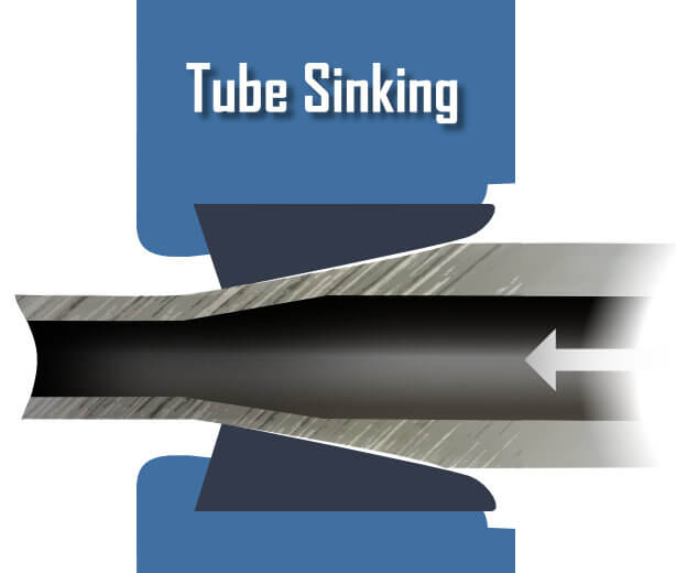
Sinking DOM Tube process without internal support of mandrel.
Sinking Drawing
This drawing process provides no internal ID support. In other words, there is no mandrel present in this process. Additionally, sinking is typically comes after a rod drawing. Both plug drawing and sinking work to reduce the tube OD (Outside Diameter) while minimizing the ID (Inside Diameter) measurements.
In some cases, Tube Sinking is the first die reduction in a series of reductions which may include Fixed Plug drawing as the final one.
Sinking Drawing Advantages
By far the biggest advantage of Sinking is cost. Applications include low-cost outdoor furniture, tent support, temporary shelters, and other structures that do not require exceptional strength or surface quality.
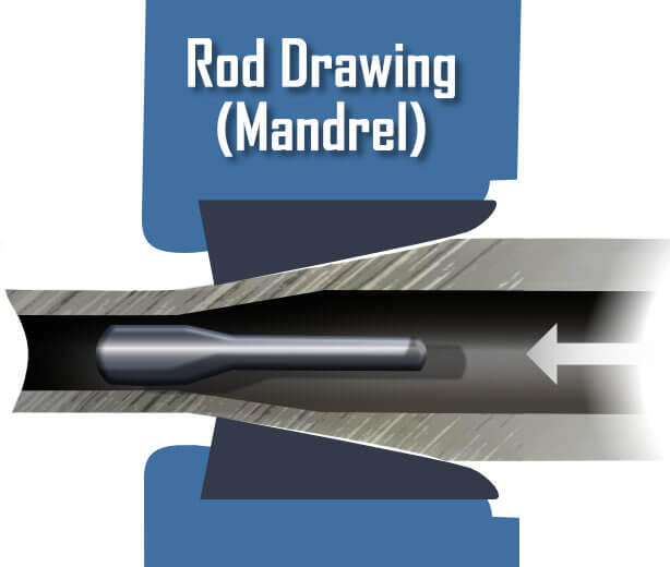
Rod Drawing – DOM Drawn Over Mandrel
Rod Drawing
Much like fixed plug drawing, rod drawing is pulling the hollow (tube blank) through a die and over a mandrel. However, its use is rarely alone or without further drawing . Extracting the rod requires the process of reeling.
Rod Drawing Advantages
The advantages of drawing are the high speed and reductions that can be achieved. Step up takes less time. Therefore, shorter runs are achievable. However, the disadvantages is that it’s a multi-person task and requires additional drawing to remove tooling (spiral) marks. Furthermore, most runs extend to a limit of 100 feet (30.48 m) or less.
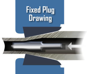
DOM Fixed Plug Mandrel Cold Drawing Process
Fixed Plug Drawing
This drawing method is the oldest for stainless steel. Due to the fact that superior ID surfaces can be obtained. Though, the tube reductions are limited and the operation is slower than other drawing methods.
Fixed Mandrel Advantages
The primary advantage Fixed Plug Cold Drawing process is that it produces a very clean Inside Diameter (ID) surface. Also, important is that it’s possible to make precision adjustments to the ID in order to meet very tight tolerances.
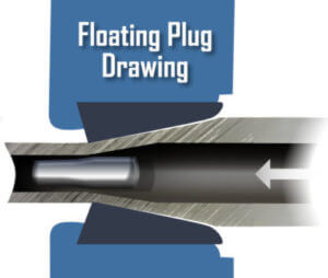
DOM Floating Plug Mandrel
Floating Plug Drawing
Floating Plug method has been the preferred drawing process for stainless steel. It’s also the choice when very long and good ID surface quality is a requirement. Due to the fact that very long lengths of tube can be produced, lubrication, speed (flow rate), die and mandrel are all critical.
Floating Mandrel Advantages
There are several advantages in Floating Plug DOM. Most importantly is ability for higher yields. In other words, its extremely long length capacity of up to 1,000 feet (0.3 km).
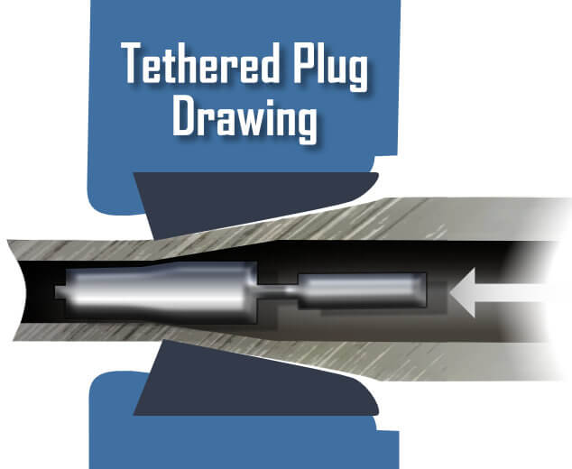
DOM Tethered Plug Drawing or semi floating
Tethered Plug Drawing
Tethered Plug Drawing is a mix between fixed and floating plug drawing. In other words, the mandrel floats within the tube though it is tethered to a rod. Therefore, this process offers the benefits of a superior ID surface.
Tethered Plug Advantages
The main advantage in Tethered Plug DOM is superior ID surface. In applications which require thermocouple sheathing, tethered plug is preferable.
References
Kartik, Ramanan (1995). Computer Aided Design Of Dies For Cold Drawing Processes (Master thesis). Ohio University. https://etd.ohiolink.edu/!etd.send_file?accession=ohiou1179943933&disposition=inline
Neves, Frederico Button, Sergio Caminaga, Celio Gentile, Fernando (2005). Numerical and Experimental Analysis of Tube Drawing With Fixed Plug. State University of Campinas. https://www.researchgate.net/publication/245405922_Numerical_and_experimental_analysis_of_tube_drawing_with_fixed_plug

Comments (3)